

The flame sensor is a vital part of the modern-day gas furnace. It ensures that we do not allow gas through the furnace unless a flame has been established. Flame sensors operate via a process called flame rectification. This is the replacement to the previous era thermocouple and its accompanying standing pilot.
How does flame rectification work?
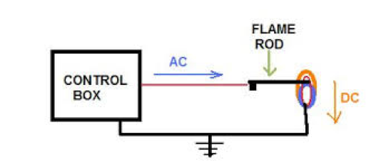
- As the heating cycle begins, the furnace control board emits a low current voltage to the flame sensor. This is usually between 40-80 volts AC. Yes, that is correct … a flame sensor has line voltage on it during furnace operation.
- As ignition occurs, the flame spreads across all the burners in the furnace where it will reach the last burner and the flame sensor rod. The flame itself is a conductor and the voltage will pass across the flame to the furnace chassis.
- During the passing of voltage across the flame, the incoming AC voltage is rectified to DC Voltage. This voltage, which is now direct current (DC), then flows to the grounded burner assembly. This flow of current from the flame sensor rod to the furnace chassis ground is “sensed” by the board and is the process by which the board verifies we have a successful ignition.
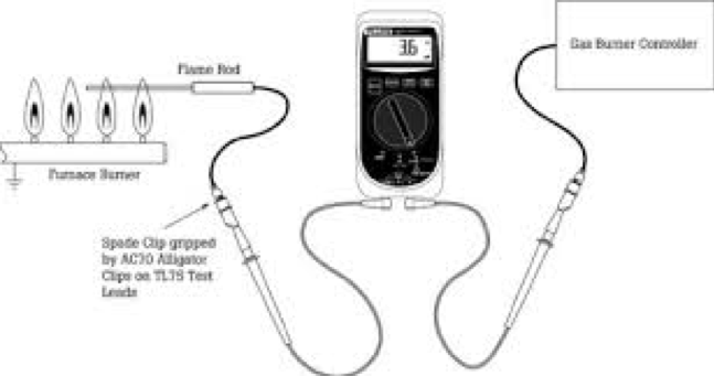
Flame rectification is measured in DC micro-amps. This is symbolic of the extremely low current being flowed from the flame sensor back to the furnace ground. Generally, the furnace will see a production of 1 to 10 DC micro-amps. In order to test your furnace for proper flame rectification you will need a digital multimeter that is capable of measuring DC Micro-amps. The symbol for DC Micro-amps is “μA”. During testing your multi-meter will become part of the flame sensor circuit and will be able to read the flame rectification signal:
Flame sensors do not particularly fail. They are just a piece of metal that sticks out into the furnace flame. However, they do require some maintenance: like any conductor exposed to the environment they can become corroded or rusty and this creates an insulating layer that reduces the ability of the sensor rod to conduct electricity well. Flame sensor rods will need cleaning periodically and this is often recommended on annual preventative maintenance. To clean the flame sensor rod it is best to use either a stiff steel brush or possibly some steel wool. You want to avoid scratching the flame sensor rod as these scratches can allow for the build-up of foreign material that may inhibit the ability of current to flow.
Another area of concern is to ensure that we have nothing interfering with the AC signal prior to the end of the flame sensor rod. Some areas where issues occur are the wire itself feeding the flame sensor; sometimes these become pinched as they work their way from the main control board up to the burner compartment. Also, if the ceramic that insulates the flame sensor rod as it is mounted to the burner assembly becomes cracked. Both will allow the signal to become grounded prior to being rectified to DC and establishing current flow. Ironically, this is often had to diagnose because it does not create an electrical short … the furnace just will not establish flame.
Diagnosing a furnace issue related to flame rectification is not hard, but it certainly becomes easier when you fully understand what the furnace is looking for. Hopefully, this will prove to be a good foundation for understanding flame sense.