


Robert Frost once famously fretted over which two diverging roads in the woods to take. He presented the case of a traveler that has come to a crucial decision that must be made. The same theme often rings true in HVAC diagnosis. The technician finds themselves at a diagnostic crossroads, if you will, and a choice must be made:
- The variable-speed blower motor will not run. Is it the board or is it the motor/module?
- My inverter system is throwing an error code. The service manual says it could be the compressor or the board.
- My HVAC system will not communicate. Is it the indoor control board, the outdoor control board, or the wiring?
Today I am going to review troubleshooting an inverter compressor and the control that drives it. Often in analyzing service manuals you find flow charts that look like this:
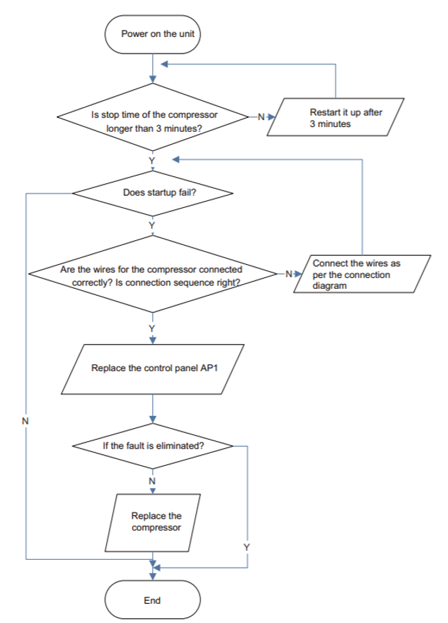
These types of charts are not particularly helpful and will generally just result in lots of parts being changed. So today, let’s take a deeper look into the inverter compressor and how the control board drives that compressor.
The compressor itself is a 3-phase AC voltage compressor. Most inverter units utilize a rotary style compressor, though some on the market utilize scroll types. These compressors use terminal designations of W | V | U, as opposed to more traditional terminal designations like C | R | S. Generally, we analyze the windings to ensure they are in good condition and they are not compromised to the outer shell of the compressor (ground). This begins by checking each winding to the others:
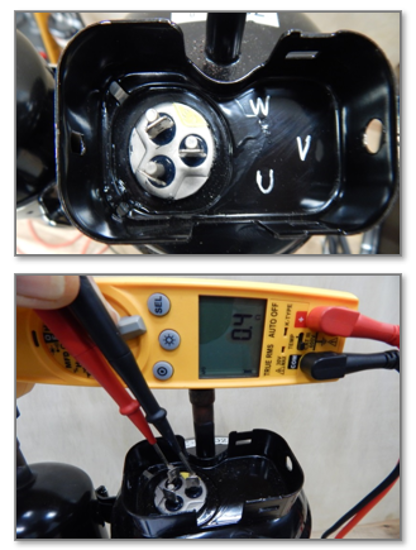
Make sure power to the system is cycled off. Please allow the system to sit for several minutes to bleed any power out of the control board capacitors. Unhook the wires from the compressor and set your meter to ohms. Check U-W | U-V | V-W. The resistance for each test should be the same and will generally be around the .5 to 1.0-ohm range. This is be an indication that the compressor windings are balanced and in good overall condition. The next test is to ensure the compressor is not grounded, or in some cases, partially grounded. To begin, test each terminal to ground with a meter set to ohms. It should read O.L., indicating an open connection. If there is a resistance reading to ground, the unit has a bad compressor. You may take this test further if you possess a megohmmeter; this is a specialized type of meter used to measure the electrical resistance of insulators. In this case it allows us to ensure the compressor windings have adequate insulation preventing them from touching one another or the compressor shell. Specific mega-ohm readings can vary from manufacturer to manufacturer, but generally for a compressor we are looking for greater than 500 mega-ohms resistance between all the individual terminals and ground.
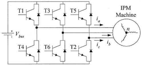
After looking at the compressor as an individual component, our next step is to look at what drives the compressor. Inverter compressors are generally driven by an IPM. Now, before I discuss the IPM and how to troubleshoot it … let us have a quick refresher on the basic premise of an “inverter”. An inverter drive works by taking AC voltage and first converting it into DC voltage, then the DC voltage is usually cleaned with capacitors and possibly a DC choke before it is connected to a network of power transistors to turn it into three phases for the motor. This network of power transistors of a small inverter drive is an ‘intelligent power module’ (IPM). The IPM successfully “inverts” the DC voltage into a simulated form of 3-phase AC voltage.
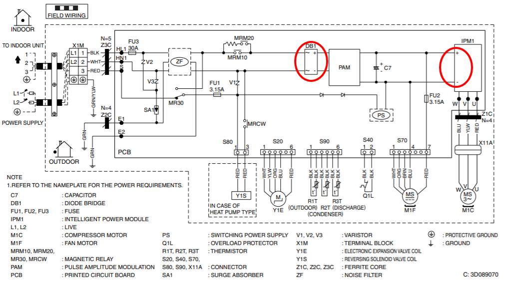
There are times where the IPM will fail. When this happens, power is not able to switch properly to operate the compressor and the control board will fault out on an IPM protection fault. This can mean a bad compressor, a bad control board, or possibly both. Without the knowledge to test each component individually we are blindly guessing. To test the IPM we will need a multi-meter with a diode test function ( ). This symbol is often near the same function as continuity on a multi-meter. It will provide a small electrical signal that we will send through the IPM. Depending on how the signal flows through the IPM we will be able to determine if the IPM is functioning properly or not. You will need to make sure the power is turned off to the system and the compressor is not plugged into the control board. Begin by locating the positive and negative test points on the control board:
1). Place a negative meter lead on the positive test point. Then check each terminal of the control board IPM [U | V | W] with the positive meter lead. You should receive a reading on your meter of 0.3-0.7VDC. This indicates this section of the IPM is properly flowing power. A reading of 0 or O.L. would indicate power is not flowing properly through the IPM.
2). Place your positive meter lead on the negative test point. Then check each terminal of the control board IPM [U | V | W] with the negative meter lead. You should receive a reading on your meter of 0.3-0.7VDC. This indicates this section of the IPM is properly flowing power. A reading of 0 or O.L. indicates power is not flowing properly through the IPM.
3). Place your negative meter lead on the negative test point. Then check each terminal of the control board IPM [U | V | W] with the positive meter lead. You should receive a reading on your meter of O.L. This indicates this section of the IPM is properly controlling the flow of power through the IPM.
4). Place your positive meter lead on the positive test point. Then check each terminal of the control board IPM [U | V | W] with the negative meter lead. You should receive a reading on your meter of O.L. This indicates this section of the IPM is properly controlling the flow of power through the IPM.
By familiarizing yourself with these diagnostic concepts for testing an inverter compressor and the control that drives it, you will ensure you are prepared to make an accurate diagnosis. You will be able to tell if the issue is in the compressor, the control board, or both. You will have facts to support your diagnosis. There may be multiple paths diverging on your service call, but you will know which path to choose. In the end, that makes all the difference.