

On a recent cold afternoon, I received a call from a frantic service technician. He diagnosed a faulty gas valve in a gas furnace, arrived on the job site with a new gas valve, taken time to ensure the new valve was installed properly, and then observed in horror as the exact same failure to ignite happened with the new valve. Now, let us all be honest with ourselves … after all, nobody is watching … we have all been that technician. We have all experienced the horror of realizing our diagnosis is wrong. Not a good feeling … and far worse if the furnace is in a closet and the homeowner is standing over your shoulder.
After the technician took a few deep breaths and regained composure, we began to go back through the furnace together.
“Tell me what exactly the furnace is doing,” I asked.
“Well, the inducer motor comes on … the igniter glows red hot … and I hear a click, but nothing happens. So, I diagnosed a bad gas valve,” he said.
“Ok,” I said, “That at least tells us that your limit switches are closed since you initiated the heating sequence and the induced draft motor cycled on. Also, obviously, the pressure switch is pulling in since your hot surface igniter is receiving power. Did you have 24-volts at the gas valve?” I said.
“Yes, I did” he replied.
I probed a little deeper;
“What wires were you reading voltage on?” I asked
“I had 24-volts between common and hi” was his reply.
“What about on low or “M” for main valve?” I asked.
“But I was calling for high stage heat.” the technician replied.
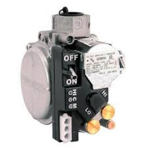
We found the disconnect in our troubleshooting. Yes, the furnace was a two-stage model. Yes, the call for heating was for the highest stage. The problem was that the gas valve was not receiving signal voltage for the “main valve”. When you are looking at a gas valve on a two-stage furnace you will see three terminals:
H = High Stage Solenoid (W-2 | High Fire)
C = Common
M = Main Valve (W-1 | Low Fire)
The valve uses the low fire signal to control the main plunger in the valve and allow for gas to flow through. The high fire solenoid increases the amount of gas allowed to flow through to increase heating capacity. This is similar to how two-step compressors operate. The signal for low stage cooling (Y1) engages the main relay that sends power to the compressor while the signal for high stage cooling (Y2) merely controls a solenoid for the normally open unloader ports. The compressor cannot operate without power to the windings which is provided by the main relay. The high stage signal merely increases the volume of refrigerant allowed to flow through the compressor. The same concept as a two-stage gas valve where the “high” stage allows a large volume of gas to flow through the valve.
Since our main valve controls whether any gas will be allowed to flow through, this is the optimal place to put in safeties we might want in series with that gas valve. A common safety you will find in many condensing furnaces (90-AFUE or higher) is a front cover switch. The front cover switch is present to ensure that the furnace collector box is not full of condensation. If the furnace is not able to effectively drain its condensation, then the front cover switch port will be blocked with water and the switch will not be able to close. This will interrupt the main valve signal to the gas valve for the purpose of stopping the production of condensation. See the picture below for an example:
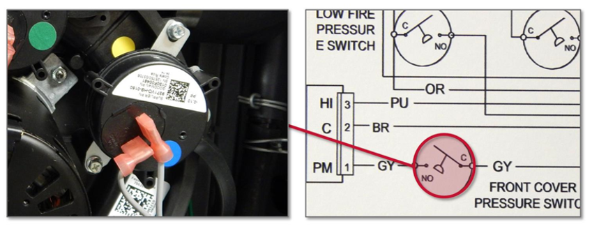
In normal pressure switch applications where we are proving the induced draft motor can effectively draw combustion air and vent the flue gas, the pressure switch must be open at the beginning of the heating sequence and then closed once the induced draft motor powers on. The front cover switch is a normally open switch that will close upon the induced draft motor powering on; this is because the induced draft motor will place the entire heat exchanger and collector box under a negative pressure as it draws combustion air through the heat exchanger and vents the byproducts of combustion. Unlike standard pressure switches, the front cover switch may be bypassed for testing purposes. So, before you condemn the gas valve: check for signal voltage between main valve and common, if you do not have voltage present then check across your front cover switch to see if is open, and if all else fails … try a testing jumper across the switch to see if that restores voltage to the gas valve.
Another quick pro-tip: When you are working on a condensing furnace you can easily use the pressure switches to narrow down where an issue may be. If the front cover switch is opening, then the issue is somewhere from the collector box moving out the drain lines. However, if the low/high fire switch is opening, then the issue is somewhere from the induced draft assembly moving out the flue pipe. This tip can help you narrow down where your issue may be quickly by eliminating the areas where you need not focus.